
Most sewing machine diagrams look simple until you compare them with the machine sitting in front of you. A control may be in a different place, hidden behind a cover, replaced by a button, or shown on a screen instead of a dial. The machine may still perform the same basic job, but the way you access that function can differ significantly by brand, age, and model type.
This guide explains the parts that matter during setup, sewing, cleaning, and troubleshooting. It also separates universal stitch-forming parts from model-specific controls, so you can understand your own machine without assuming that every online diagram must look identical.
How the main sewing machine systems work together
A sewing machine forms a stitch by coordinating several systems at the same time. The upper thread travels from the spool through guides, the tension system, and the thread take-up lever before reaching the needle. The needle carries that thread down through the fabric. Below the needle plate, the hook mechanism catches the upper-thread loop and passes it around the bobbin thread. The feed dogs then move the fabric forward while the presser foot keeps it stable.
This sequence depends on timing. The needle, hook, take-up lever, and feed dogs must move in the correct relationship. That is why a problem that appears to be “just the thread” may actually begin with an incorrectly inserted needle, a raised presser foot, a jammed bobbin area, or fabric being pulled against the feed system.
Parts found on the top of the machine
Spool pin
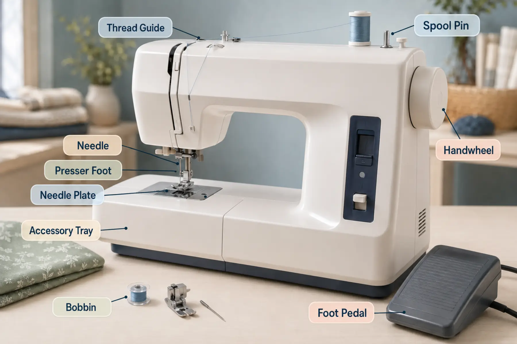
The spool pin holds the upper-thread spool. It may be vertical, horizontal, foldable, or removable. Horizontal spool pins usually require a spool cap that is wide enough to secure the spool without squeezing it. Vertical pins may use a felt pad under the spool to reduce vibration.
The spool must unwind in the direction shown in the manual. If the spool cap is too small, the thread may catch on the spool edge. If it is too large and pressed tightly against the spool, the thread may not unwind freely.
Auxiliary spool pin
An auxiliary spool pin is used for twin-needle sewing, bobbin winding, or a second spool. Some machines store it in the accessory compartment and require it to be inserted only when needed.
Bobbin-winder spindle
The bobbin-winder spindle holds the empty bobbin during winding. On many machines, sliding the spindle to the right engages bobbin-winding mode and disengages normal needle movement. On others, winding mode is selected electronically.
A machine that powers on but will not sew may simply still be in bobbin-winding mode. Always return the spindle to the sewing position after winding.
Bobbin-winder stopper
The stopper limits how full the bobbin becomes. It should stop winding before the thread reaches the bobbin rim. Do not continue winding by force after the bobbin is full because an overfilled bobbin can fit poorly, rub against the case, or feed unevenly.
Upper thread guides
Thread guides control the route from the spool to the needle. They prevent the thread from wandering, twisting excessively, or entering the tension system at the wrong angle. Missing one guide can cause inconsistent tension or repeated thread breakage even when the rest of the threading path looks correct.
The upper-thread control system
Tension discs
The tension discs regulate resistance on the upper thread. They are usually hidden behind the front cover or tension dial. Raising the presser foot opens the discs so the thread can enter between them. Lowering the presser foot closes the discs and applies the selected tension.
This is why upper threading should normally be done with the presser foot raised. Threading with it lowered can leave the thread outside the discs and cause loops or “bird nesting” underneath the fabric.
Upper-tension control
Mechanical machines commonly use a numbered dial. Computerized models may still use a dial, or they may display a recommended setting and adjust tension electronically. A screen does not always mean the machine has automatic tension, so check the manual before assuming the machine will correct every fabric change itself.
Thread take-up lever
The take-up lever moves up and down with the needle. It releases thread as the needle descends and removes slack as the stitch tightens. The thread must pass through its opening or hook. If the lever is hidden inside the machine, turn the handwheel toward you until it rises into view.
A missed take-up lever often causes loose thread underneath, thread whipping around the needle area, or a machine that sews briefly before tangling.
Check spring
The check spring is a small spring in the upper-thread path that helps maintain temporary tension as the take-up lever moves. Beginners usually do not adjust it, but recognising it can prevent confusing it with a broken guide. Adjustment or repair is normally a service task.
Needle-area parts and what each one controls
Needle bar
The needle bar holds the needle clamp and moves the needle vertically. Its height and timing are calibrated internally. Beginners should not loosen the needle bar itself.
Needle clamp and needle-clamp screw
The needle clamp secures the needle to the needle bar. The needle must be pushed fully upward before the clamp screw is tightened. A needle that sits too low changes its relationship with the hook and may cause skipped stitches, thread breakage, or needle strikes.
Needle
The needle carries the upper thread through the fabric. Its main features include the shank, shaft, scarf, groove, eye, and point. The flat side of the shank faces a model-specific direction, commonly toward the back on many domestic machines, but not universally. Follow the manual rather than copying another machine.
Needle type and size must suit the fabric. A dull, bent, incorrectly inserted, or unsuitable needle is one of the most common causes of skipped stitches, fabric damage, popping sounds, and thread shredding.
Needle threader
An automatic needle threader is a small hook mechanism that pulls a loop of thread through the needle eye. It works only when the needle is at the correct height and the needle size is compatible. It should move gently. Forcing it can bend the hook.
Needle plate or throat plate
The needle plate is the metal surface beneath the presser foot. It contains the needle opening, feed-dog slots, and often seam-guide markings. A straight-stitch plate has a small round opening and supports delicate fabric well, while a zigzag plate has a wider opening to allow side-to-side needle movement.
Never select a wide stitch while a straight-stitch plate is installed. The needle can strike the plate and break.
Seam guides
The numbered lines on the needle plate help maintain a consistent seam allowance. The measurement refers to the distance from the needle position to the selected guide line, so moving the needle left or right changes the effective seam allowance.
The presser-foot system
Presser foot
The presser foot holds fabric against the feed dogs. Different feet support different tasks, such as zippers, buttonholes, blind hems, quilting, rolled hems, and overcasting. A standard zigzag foot is usually the default foot for general sewing.
Presser-foot holder or ankle
The holder connects snap-on presser feet to the presser bar. Some feet snap onto the holder, while others replace the holder and screw directly to the presser bar. Confusing these systems can make a compatible foot appear not to fit.
Presser-foot lifter
The lifter raises and lowers the presser foot. It may be located behind the needle area, beside the head, operated by a knee lift, or controlled electronically on some advanced machines. The machine generally needs the foot lowered before sewing so the tension system and feeding mechanism work normally.
Presser-foot pressure control
This control changes how firmly the foot presses on the fabric. Not every machine provides manual adjustment. Reducing pressure may help some knits or delicate fabrics; increasing it may help layers feed consistently. It should not be confused with upper-thread tension.
Walking foot and dual-feed system
A walking foot adds top feeding to help multiple layers move together. Some computerized machines include a built-in dual-feed system instead. These are not the same as ordinary feed dogs, but both aim to reduce layer shifting.
Feed dogs, stitch length, and fabric movement
Feed dogs
Feed dogs are the toothed metal bars that rise through the needle plate and move the fabric. Their movement is synchronized with the needle. You guide the fabric, but the feed dogs determine the normal rate of travel.
Pulling fabric from behind can bend the needle, create uneven stitches, and disturb timing. Supporting the fabric's weight is helpful; forcing its movement is not.
Drop-feed control
The drop-feed lever lowers the feed dogs for free-motion quilting, darning, or button sewing. It may be on the back, under the free arm, or inside the accessory compartment. Some feed dogs do not rise immediately when the lever is reset; turning the handwheel one full rotation may re-engage them.
Stitch-length control
Stitch length changes how far the feed dogs move the fabric between needle penetrations. A longer setting creates longer stitches; a shorter setting creates more stitches per inch. On a mechanical machine this is often a dial or lever. On a computerized model it is usually adjusted with buttons and shown on the display.
A medium stitch length is appropriate for many general woven fabrics, but thick fabric, topstitching, gathering, and delicate materials may need different settings.
The bobbin system below the needle plate
Bobbin
The bobbin stores the lower thread. Bobbins that look similar may differ in height, diameter, curvature, or material. Using the exact class specified for the machine is essential. The wrong bobbin can affect tension, jam the case, or damage the hook area.
Top-loading bobbin
A top-loading or drop-in bobbin sits horizontally beneath a clear cover. The thread follows a marked path through a slot and tension spring. The direction of unwinding matters.
Front-loading bobbin
A front-loading bobbin sits inside a removable bobbin case, which is inserted vertically into the shuttle or hook race. The thread must pass through the slot and under the bobbin-case tension spring.
Bobbin case
The bobbin case holds the bobbin and applies lower-thread tension. On front-loading systems it is removable. On many top-loading systems it remains in the machine. The small tension screw is not a first-line beginner adjustment. Mark its original position before any authorised adjustment.
Hook or shuttle
The hook catches the upper-thread loop behind the needle and carries it around the bobbin. Rotary hooks rotate continuously; oscillating hooks move back and forth. Both perform the same basic stitch-forming function.
Hook race
The hook race is the path in which the hook moves. Thread fragments and lint can collect here. Clean only the areas the manual identifies as user-serviceable, and reinstall every retaining ring or cover correctly before sewing.
Stitch and motion controls
Handwheel
The handwheel manually raises and lowers the needle. Turn it in the direction specified by the manufacturer, commonly toward you. Turning it backward can create slack in the thread path or disturb a partially formed stitch on some machines.
Foot controller
The foot controller regulates motor speed. It should sit on a stable surface where the whole foot can rest comfortably. A controller matched to another machine may have a different electrical specification and should not be substituted casually.
Reverse control
Reverse makes the feed dogs move fabric backward to secure many ordinary seams. Mechanical machines often use a lever or button that must be held. Computerized machines may use a reverse button, reinforcement button, or programmed locking stitch. These functions are not always identical.
Stitch selector
A mechanical machine uses one or more dials to select stitch patterns. A computerized machine uses numbered buttons, arrow keys, a touch panel, or a screen menu. The selected stitch may automatically load recommended length and width settings.
Stitch-width control
Stitch width controls side-to-side needle movement for zigzag and decorative stitches. On some straight-stitch settings, it changes needle position instead. Before selecting a wide stitch, confirm that the installed presser foot and needle plate provide enough clearance.
Needle-position control
This control moves the needle left, centre, or right. It helps with edge stitching, zippers, seam allowances, and precise topstitching. Computerized models may offer many incremental positions, while mechanical models often provide fewer.
Parts and controls mainly found on computerized machines
LCD or touch display
The display shows the selected stitch, recommended foot, stitch length, width, needle position, and sometimes warnings. A display is an interface, not the stitch-forming mechanism itself. The needle, hook, bobbin, feed dogs, and tension path still perform the physical work.
Start-stop button
This button lets the machine sew without the foot controller on supported models. The machine may refuse to start if the presser foot is raised, the bobbin winder is engaged, or an incompatible mode is selected.
Speed-control slider
The speed slider limits the maximum sewing speed whether the machine is controlled by pedal or start-stop button. It is especially useful for beginners, curves, appliqué, and detailed work.
Needle up-down button
This sets whether the needle stops raised or embedded in the fabric. Needle-down is useful for pivoting corners and maintaining position on curves.
Automatic thread cutter
The thread cutter trims upper and bobbin threads at the end of a seam. It depends on a clean cutting area and compatible thread. Thick specialty thread may not be suitable.
Automatic reinforcement and tie-off
These controls secure stitches using programmed short stitches rather than ordinary reverse feeding. They are useful for delicate or decorative work where a bulky reverse section would be undesirable.
Stitch memory
Stitch memory stores combinations, alphabets, or repeated decorative sequences. It does not replace correct threading, needle choice, stabilizer, or test sewing.
Sensors and error messages
Computerized models may monitor presser-foot position, buttonhole lever position, bobbin winding, thread breakage, or safety conditions. An error message is often a protective response rather than an electronic failure. Read the exact message before switching settings randomly.
Internal parts beginners should understand but not adjust
Motor
The motor drives the machine. A mechanical machine still uses an electric motor; “mechanical” describes the control system, not the absence of electricity.
Drive belt
The belt transfers motor motion to the upper shaft. A worn or loose belt may cause slipping, slow response, or a motor sound without normal needle movement. Belt replacement may require service access.
Upper and lower shafts
These shafts coordinate the needle bar, take-up system, hook, and feed mechanism. Their relationship is part of the machine's timing.
Gears and cams
Gears transfer motion; cams create stitch patterns in many mechanical machines. Cracked gears, hardened lubricant, or damaged cam followers are repair issues, not user settings.
Timing mechanism
Timing describes the relationship between the needle and hook. If the hook reaches the needle too early or too late, the machine may skip stitches or fail to form them. Timing should not be adjusted until threading, needle insertion, needle condition, and bobbin setup have been ruled out.
Circuit boards and stepper motors
Computerized models use circuit boards and electronic motors to control stitch selection, needle position, feed movement, and automated functions. These parts should be diagnosed by a qualified technician.
How parts change across different sewing machine types
A basic domestic sewing machine uses one needle and a lockstitch system. A serger or overlocker uses loopers, multiple tension paths, cutting blades, and differential feed. An embroidery machine adds a hoop carriage and embroidery unit. A coverstitch machine uses multiple needles and loopers to create stretch hems.
These machines share some familiar terms, but their threading and stitch-forming systems are not interchangeable. A diagram for an overlocker should not be used to thread a standard lockstitch machine.
Quick reference: part, function, and common warning sign
Which parts require regular cleaning
Lint accumulates fastest around the bobbin area, feed dogs, needle plate, and thread cutter. Switch off and unplug the machine before cleaning. Remove the needle, presser foot, bobbin, and needle plate only as directed by the manual. Use the supplied brush or a soft lint brush.
Do not blow lint deeper into the machine. Do not add oil unless the manufacturer specifically identifies oiling points. Many modern machines are designed for technician lubrication rather than routine user oiling.
Parts beginners should not adjust casually
Hook timing or needle-bar height
Internal gears, belts, cams, or shafts
Bobbin-case tension screw without a clear reason
Electronic boards, wiring, sensors, or motors
Presser-bar height or feed-dog height
Factory-set tension springs and timing screws
Before assuming an internal part needs adjustment, rethread the machine, insert a fresh correct needle, confirm bobbin type and direction, return to a basic straight stitch, and test on stable woven fabric. Continue with the main troubleshooting guide if the problem remains.
How to identify the parts on your own machine
Start with the exact model number, usually printed on the front, back, underside, or identification plate. Download the correct manual rather than relying on a manual for a similar-looking model.
With the machine switched off, locate the spool pin, thread guides, take-up lever, needle clamp, presser-foot lifter, bobbin cover or bobbin case, handwheel, reverse control, stitch selector, and feed-drop control. Then follow the setup process in How to Set Up Your Sewing Machine.
Photograph the machine before removing covers or accessories. Keep the accessory tray, bobbins, feet, spool caps, and screwdrivers labelled. A small unidentified part is much easier to understand when you know where it was stored.
Frequently Asked Questions
Sewing machine parts questions
What are the main parts of a sewing machine?
The main parts include the spool pin, thread guides, tension system, take-up lever, needle bar, needle, presser foot, feed dogs, needle plate, bobbin system, handwheel, stitch controls, reverse control, and foot controller or start-stop controls.
Are the parts of mechanical and computerized sewing machines different?
Their core stitch-forming parts are mostly the same. The main differences are in the controls, displays, sensors, automatic functions, and how stitch settings are selected.
Which sewing machine parts should a beginner clean?
A beginner can usually clean lint from the bobbin area, feed dogs, and removable needle plate area according to the manual. Internal covers, belts, gears, wiring, and timing mechanisms should be left to a qualified technician unless the manufacturer says otherwise.
Why is it important to learn sewing machine parts?
Knowing the parts makes threading, setup, stitch selection, cleaning, and troubleshooting much easier. It also helps you follow the manual and understand whether a problem is caused by threading, feeding, the needle, the bobbin, or a control setting.
Which parts should not be forced?
Do not force the handwheel, stitch selector, bobbin cover, needle clamp, presser-foot holder, or removable plates. Resistance usually means the part is misaligned, locked, or being moved while another setting is engaged.
Learn the system, not just the labels
Memorising part names is useful, but understanding how the parts work together is what makes sewing easier. The spool pin supplies thread, the tension system controls it, the take-up lever manages slack, the needle carries it through the fabric, the hook joins it with the bobbin thread, and the feed system advances the material.
Once that sequence makes sense, setup instructions become clearer and troubleshooting becomes more logical. You stop changing random settings and start checking the part most closely connected to the symptom.